Call us now
07971459752
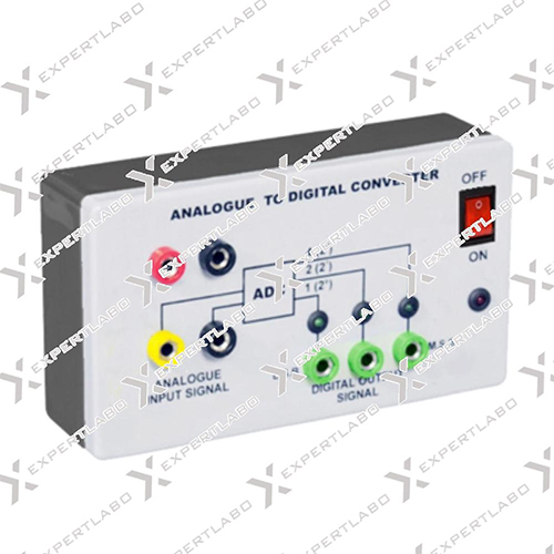
Analogue To Digital Converter

Analogue To Digital Converter Specification
- Shape
- Rectangular Module
- Speed Range
- Up to 500 kSPS (Kilo Samples per Second)
- Accuracy
- 0.5% FSR (Full Scale Range)
- Power Supply
- External DC Power Adapter
- Temperature Resistance
- 0C to 70C Operating Range
- Features
- High Accuracy Conversion, Low Power, Easy Interface, LED Indicator
- Control Type
- Microcontroller/Interface Controlled
- Type
- Analogue to Digital Converter
- Dimension (L*W*H)
- 120mm x 75mm x 25mm
- Equipment Type
- Electronic Circuit Module
- Equipment Materials
- High-grade PCB, Electronic Components, Metal Connectors
- Power
- 3W
- Voltage
- 5V DC
- Material
- Plastic/PCB/Metal
- Application
- Signal Conversion, Industrial Automation, Data Acquisition, Instrumentation
- Protection
- Over-voltage/Reverse Polarity Protection
- Supported Resolution
- 8-bit/10-bit/12-bit options
- Input Signal Range
- 0-5V Analogue Input
- Isolation
- Optically Isolated (Optional in certain models)
- Number of Input Channels
- 1 Channel (Multiple Versions Available)
- Compatible Devices
- PLC, Microcontroller, PC Data Interface Modules
- Operating Frequency
- 1 MHz (depends on model)
- Calibration
- Factory Calibrated
- Humidity Range
- 0-95% (Non-condensing)
- RoHS Compliant
- Yes
- Response Time
- Microseconds
- Interface Type
- Parallel or Serial (SPI/I2C/USART)
- Output Format
- Binary Digital Output
- Mounting Type
- PCB Mount/DIN Rail (varies as per design)
About Analogue To Digital Converter
Analogue to digital converter circuit internally fitted inside a plastic moulded case. Analogue signal 0-7V DC given by analogue input sockets is converted into digital output signal in 1V steps i.e. 001 for 1V, 010 for 2V and so on. Three LEDs are used for representation of binary digital signal. The output voltage against each LED directly comes out through 4mm sockets and can be used for coupling it with DAC instrument. Operating voltage for the instrument is 12V DC. For more sensitivity of lower range, a selector toggle switch marked with (0-7V/0-2V) is used
Versatile Input and Output Features
Accepting a 0-5V analogue signal, this ADC is engineered to meet a variety of precision conversion needs. Selectable resolutions (8/10/12-bit) provide flexibility for different application requirements, while binary digital output ensures seamless interfacing with digital systems.
Flexible Interface and Mounting Options
Equip your system with a choice of parallel or serial interfaces (SPI/I2C/USART) for easy integration. The converter's mounting options-PCB or DIN rail-cater to varied installation scenarios, making it ideal for industrial environments and laboratory setups alike.
Reliable and Durable Performance
With a high operating frequency of up to 1 MHz and support for up to 500 kSPS, this module handles fast signal conversion demands. It operates within a wide temperature (0C to 70C) and humidity range (0-95% non-condensing), constructed using high-grade materials for enduring industrial use.
FAQ's of Analogue To Digital Converter:
Q: How do I install the Analogue to Digital Converter module for my application?
A: The ADC module can be mounted directly on a PCB or a DIN rail, depending on your selected model. Use standard connectors for both power and signal input, ensuring proper alignment and secure connection for stable operation.Q: What benefits does the selectable resolution (8/10/12-bit) provide?
A: Selectable resolution allows users to balance between conversion speed and measurement accuracy. Higher bit resolutions (10/12-bit) deliver finer signal detail, ideal for precision tasks, while lower bits (8-bit) enable faster sampling rates and efficient processing for less demanding applications.Q: When should I use optional optical isolation in my setup?
A: Optional optical isolation is recommended when you need to protect sensitive controller circuits from voltage spikes, ground loops, or electrical noise, particularly in industrial or high-interference environments.Q: What interface types are supported and where are they commonly used?
A: This ADC supports parallel and serial interfaces, including SPI, I2C, and USART. These interfaces are widely adopted in automation equipment, microcontroller projects, and PC-based data acquisition systems for reliable, high-speed data communication.Q: How is the module calibrated and what is its accuracy?
A: Each unit is factory calibrated to ensure immediate, reliable performance with an accuracy of 0.5% FSR (Full Scale Range). This guarantees trustworthy output without the need for field calibration.Q: Can this ADC work with PLCs and microcontrollers?
A: Yes, the module is fully compatible with PLCs, microcontrollers, and PC data interface modules, making it suitable for a variety of automation and instrumentation projects.Q: What are the protective features included in the ADC module?
A: The ADC module includes over-voltage protection and reverse polarity protection as standard, reducing the risk of damage from wiring errors or unexpected voltage spikes.Tell us about your requirement

Price:
Quantity
Select Unit
- 50
- 100
- 200
- 250
- 500
- 1000+
Additional detail
Mobile number
Email

More Products in Physics Equipments Category
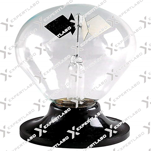
Crookes Radiometer
Price 1000 INR
Minimum Order Quantity : 1 Piece
Features : Rotates when exposed to sunlight or strong artificial light; sensitive to various light intensities; sealed vacuum bulb
Equipment Type : Physics Laboratory Demonstration Equipment
Power : Operates via light energy (no external power required)
Dimension (L*W*H) : Approx. 14 cm (Height) x 7 cm (Diameter)
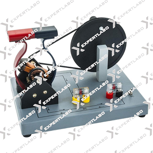
AC-DC Demonstration Dynamo
Price 500 INR
Minimum Order Quantity : 1 Piece
Features : Demonstrates AC and DC Generation, Transparent Viewing Window, Robust Construction, Easily Operated Hand Crank
Equipment Type : Demonstration Apparatus
Power : Manual (HandCrank) Operated
Dimension (L*W*H) : Approx. 20 x 10 x 15 cm
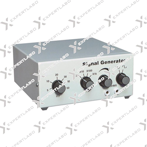
Bench Signal Generator
Price 1500 INR
Minimum Order Quantity : 1 Piece
Features : Variable frequency output, Stable signal, Compact design
Equipment Type : Signal Generator
Power : AC 220V, 50Hz
Dimension (L*W*H) : 310 x 215 x 110 mm
Double Crookes Radiometer
Price 4500 INR
Minimum Order Quantity : 1 Piece
Features : Consists of Two Bulbs, FourVane Rotors, High Sensitivity, Mounted on Stable Base
Equipment Type : Scientific Laboratory Instrument
Power : Operates by Light Energy (No External Power Required)
Dimension (L*W*H) : Approx. 120 mm x 50 mm x 160 mm
Expert Labo
GST : 06BELPA5037D2ZX
GST : 06BELPA5037D2ZX
Office 1001, Housing Board Colony, Ambala Cantt, Ambala Cantt - 133001, Haryana, India
Phone :07971459752
Mr Ajay Manocha
(Proprietor)
Mobile :07971459752
Mr- Ajay Manocha
(Proprietor)
Mobile :07971459752
- Biology Models
- Laboratory Equipment
- Pharmaceutical Lab Equipment
- Laboratory Instruments
- Physics Equipments
- Laboratory Glassware
- Laboratory Apparatus
- Hospital Equipment
- Physics Instruments
- Testing Machine
- Hospital Furniture
- Oxygen Flow Meter
- Educational Aids
- Biological Models
- Hospital Bed
- Cement Testing Equipment
- Soil Testing Equipment
- Anatomical Models
- Suction Machine
- Hospital Uniform
- Autoclave And Sterilizer
- Mortuary Cabinet
- Laboratory Microscope
- Medicine Cabinet
- Crash Cart Trolley
- Surgical Tray
- Compression Testing Machine
- Hot Air Oven
- Lab Safety Products
- Laboratory Testing And Measuring Instrument
- Survey Total Station
- Blood Pressure Monitor
- Dialysis Chair
- Examination Couches
- OT Lights
- OT Tables
- Patient Transfer and Handling System
- Ward -OT Equipments
- Examination Lights
 Send Inquiry
 Send SMS
Expert Labo
All Rights Reserved.(Terms of Use)
Developed and Managed by Infocom Network Private Limited.
Developed and Managed by Infocom Network Private Limited.

